Overexertion is one of the biggest causes of injury in manual labour. It affects over 250,000 workers every year in the United States alone. However, using modern technology, we can aim to eliminate this issue. To solve the problem, we (Jason Yin and I) developed and created an active lower-body exoskeleton powered by pneumatic cylinders and controlled by a raspberry pi microcomputer with custom software. The goal of this device is to enhance mobility and provide mechanical assistance. The exoskeleton does so by manipulating the distance between the hip and the ankle which is electronically triggered from user inputs to our microcomputer, activating the pneumatic cylinders at specific timings through the exoskeleton's software. From testing, our mechanical assistance system provides 980N of additional lifting capabilities, all while under a 0.54s response time. Through the use of this tool, humans can reduce strain on their bodies, significantly reducing injury.
As civilization carries on growing to support its increasing
population, the need for manual work only increases as there are
more houses to build, packages to ship, and materials to move.
Nevertheless, along with that work, comes the risk of strain and
injuries on the human body: Every year in the United States, 255'000
manual work labourers suffer from an injury resulting from
overexertion.
The concerning number of injuries generally stems from pushing,
lifting, and carrying objects with improper technique. However, the
reason for the improper technique often isn’t due to lack of proper
training but rather due to the object being too heavy to use proper
form on, forcing workers to place themselves in harm’s way. Using
the incredible technological advancements humans have made, however,
we have received the ability to eliminate this problem by enhancing
the user's leg strength and mobility. Through the increase in
strength, the user can once again return to focusing on their form
knowing that they have the power to do so.
To solve the problem affecting millions of people worldwide, we came
up with an active lower-body exoskeleton that uses pneumatic power
to extend and retract the leg with a superhuman amount of force.
To supply additional power to the user to reduce overexertion
injuries, we developed a rough idea for an exoskeleton that
ultimately required four different systems: Frame, Air delivery,
Battery, and Control.
We would start by brainstorming the parameters required for each
system. Then, we would research different ways to achieve these
parameters through different methods. One reason why it was
important to find different solutions was due to finding the optimal
solution. For example, when designing, we had to decide on an
actuator type to power the exoskeleton. We had three possible
solutions (pneumatic, electric motor, and hydraulic) and with them,
we determined the best powertrain through calculations. In that
specific case, our calculations were to find the actuator with the
maximum power output, lowest electricity consumption, and minimal
weight.
Once we had ample research, we moved on to design. When possible, we
would model in a 3d virtual environment to best understand the
interactions of our design with other systems. Another benefit of
modelling was the available stress and displacement tests that would
inform us of any inadequacies.
Next, we consulted professors. Through this method, we would be
aware of any oversights we may have made and would be notified of
any better solutions.
Finally, we would choose the material to prepare for manufacturing.
Strength to weight ratio was always the focus. For example, we chose
Aluminum 6061-T6 for the material.
After all systems were completed and attached, we tested the
performance of the exoskeleton through different experiments to
optimize performance.
To find the most accurate sources of information, we focused on
receiving our knowledge from university research papers,
manufacturer datasheets, and when possible, patents. Through this
methodology, we were able to be confident that our solutions and
calculations would yield the best results.
How It Works:
BATTERY/POWER:
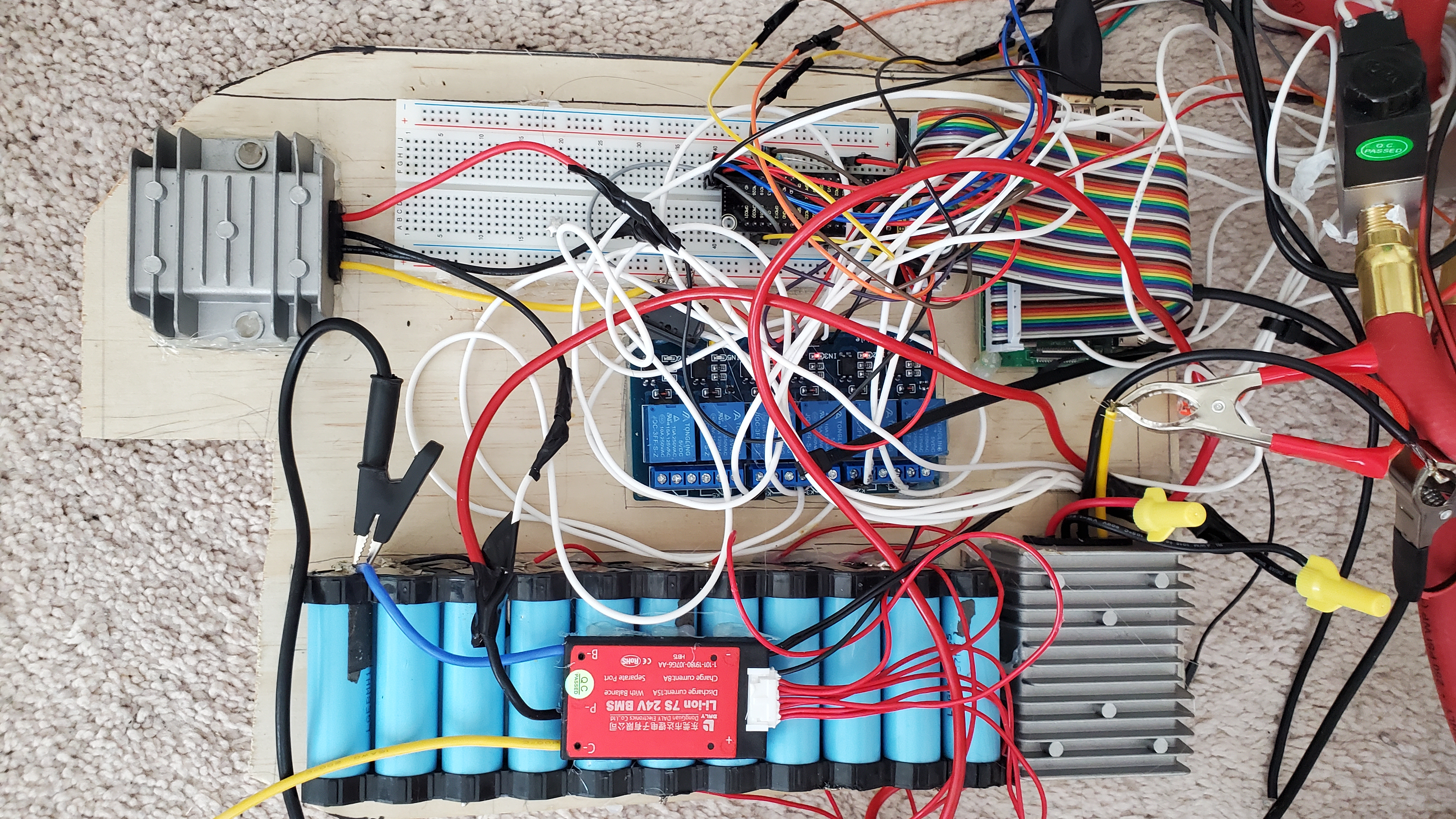
The main design criteria was high energy density to minimize weight.
To achieve that, we leveraged the latest lithium-ion technology. By
placing the batteries (18650 cells) in a 7 series 3 parallel design,
we achieved a 250 Wh battery weighing 1kg. We then used a 24V
stepdown converter for the air compressor and microcomputer.
AIR DELIVERY SYSTEM:
The air delivery system actively pumps air into the pneumatic
cylinders. To control the flow of air, we developed a design that
had an air compressor pump air into an air tank that would branch
off into the two legs. On the legs, there would be two types of
solenoid valves that control the flow using signals they receive
from the computer to either let the air go through or not. The first
layer of solenoid valves works off Pulse Width Modulation to control
airflow through the tank (More details on P.W.M in the controls
section) while the second layer uses P.W.M. to exhaust air when
necessary.
Control: (Software:
https://github.com/HOPE028/EMMAS)
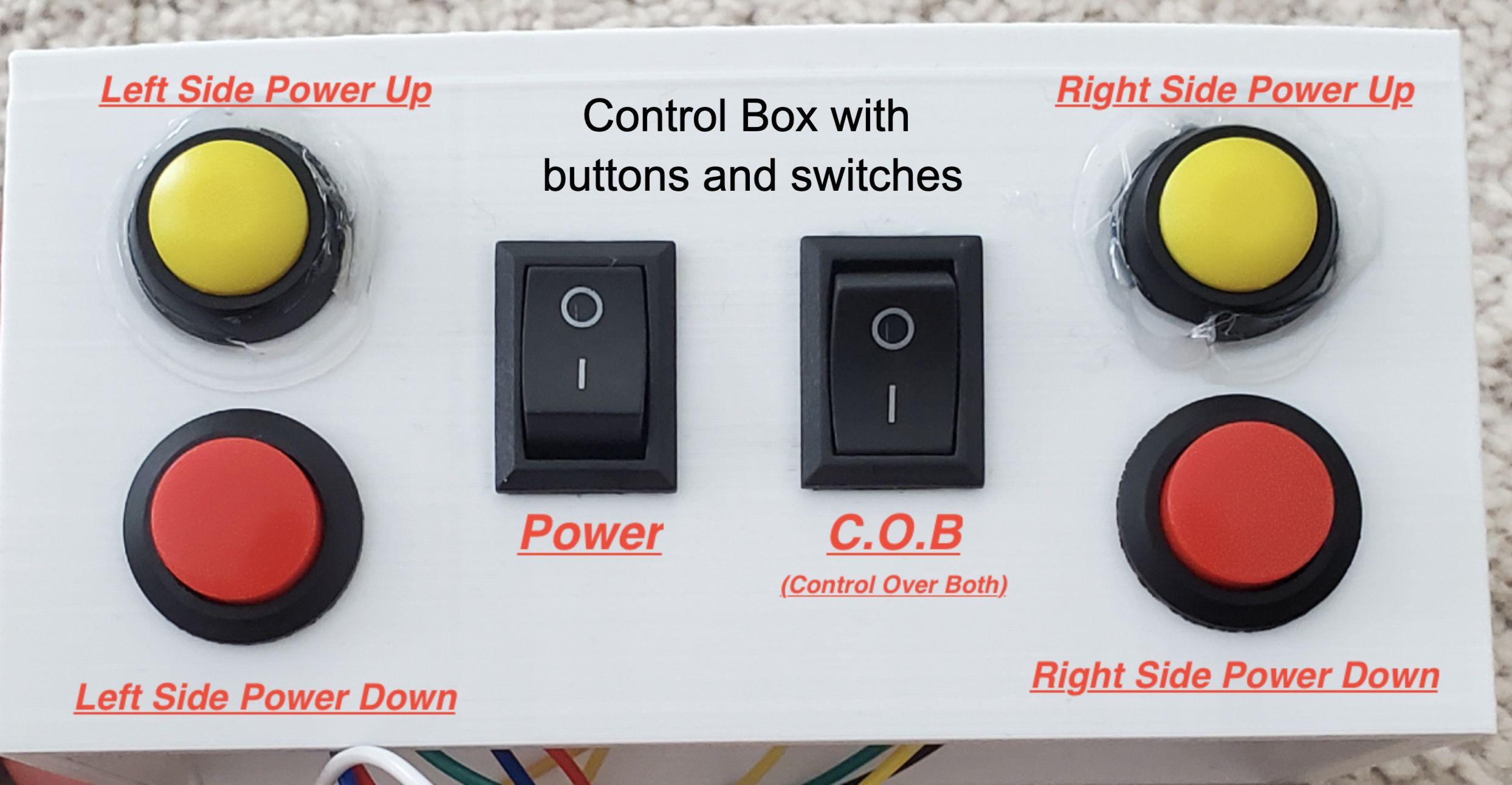
The microcomputer's role is to analyze the user’s input and send
signals to the solenoid valves. To do so, the microcomputer sends 0
and 1 bits in the form of voltage to control the valve’s state. The
valve’s state is what decides if air goes through or not. Building
on top of that, we used the P.W.M framework for precise power
control. To utilize it, we send signal changes at a high frequency
to regulate the flow rate. All inputs are received from buttons and
switches. Through the inputs, the user can change what mode the
exoskeleton is in which affects how the exoskeleton behaves.
FRAME:
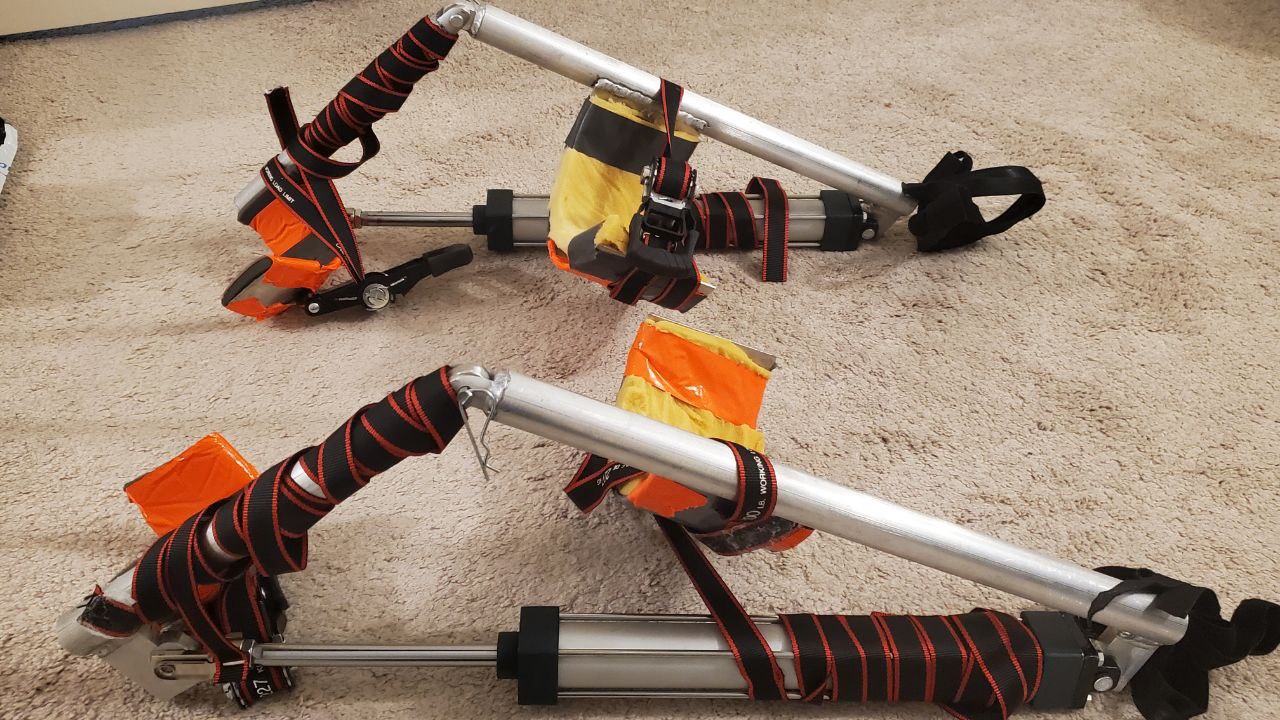
During the motion of squatting, the distance between the hip and
ankle reduces. By being able to manipulate the distance between
these two leg parts, we can mimic the leg’s movement. The pneumatic
cylinder allows us to do exactly that through the manipulation of
its own length by pumping air into its chambers when the ends are
attached to the ankle and hip.
When the pneumatic cylinder is compressing, however, it has the
ability to buckle the knee. In response, we created a frame for the
pneumatic cylinder to be attached to. The frame ensures that the
force from the pneumatic cylinder is limited to one degree of
freedom and that frame and pneumatic cylinder do not slide relative
to the body.
Testing: (Results In SO-WHAT Pictures)
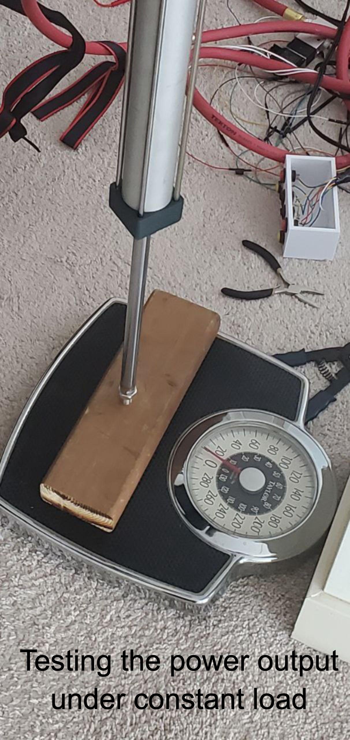
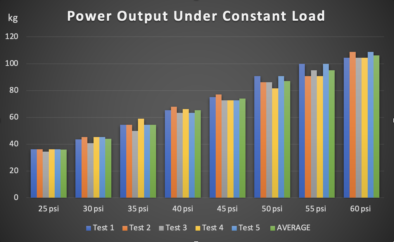
Power output under constant load:
We tested constant load performance by attaching one end of the
pneumatic cylinder to a scale and the other end to a solid base.
Through 40 different trials at 5 different pressures inside the
air-delivery system, we received performance data.
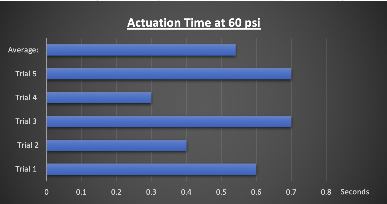
Actuation time:
We tested actuation time by setting the system at 60psi and
measuring the time between the user turning on the power and the
time it took for the system to start providing power.
The exoskeleton enhances the user's ability in ways we could not
have dreamed of. It provides incredible power at an explosive pace.
Providing up to 2940 newtons of force (at 150 psi theoretically) in
less than 0.54 seconds, the user can achieve tasks never thought to
be possible by humans. For testing equipment purposes, however, we
were never able to reach that pressure inside the chambers due to
safety concerns and air leakages stemming from prototyping. Instead,
we tested with lower pressure that a user would more realistically
use in real-life environments. The results were still very
impressive.
The first set of tests we did was reserved for seeing the power
output from the pneumatic cylinders when attached to the rest of the
system. The tests showed that when the system was running at 60 psi
(pressure inside the air delivery system), the pneumatic cylinders
could provide over 980N of force, more than enough force to lift
most users without the user's leg needing to do any work at all.
This would result in a substantial reduction of strain on the user's
body and give the user increased lifting capabilities.
Next, we tested the actuation time to test how fast a user could
receive the power of the exoskeleton. At 60 psi, the system would
take on average 0.54 seconds. That is fast enough so that the user
could carry on with their regular work pace while being aided by the
power of the exoskeleton.
The possibilities for improving the exoskeleton are endless. Some
notable optimizations would be a slightly modified frame with a more
ergonomic design, a more simple user interface that uses artificial
intelligence to predict the user's needs, and custom air compressors
and pneumatic cylinders to reduce weight and size.
We will work on these future improvements by using what we have
learnt over the span of this project such as consulting experts when
necessary, modelling more precise and thought out designs, and
having backup plans if ever something does not work out.
Research:
Taokang X., Yong Z., Ligang Q., Lin L., Chao G., (January 2022),
Weight-assisted exoskeleton knee joint plunger cylinder control
optimization,
https://www.sciencedirect .com/science/article/pii/S101 8363921001707
Fatai S., Hwa J. Y., Raja A. R. G, Norhafizan A., (November 2019),
Design and control of a wearable lower-body exoskeleton for
squatting and walking assistance in manual handling works,
https://www.sciencedirect .com/science/article/abs/pii/ S0957415819301059
Injury Data:
NSC, (April 2022), Top Work-related Injury Causes,
https://injuryfacts.nsc.org /work/work-overview/top-work- related-injury-causes/
Product Data: Wenzhou Ang Rui Machinery Co., Ltd, (April 2022)
https://www.alibaba.com/product-detail
/SC-series-Air- Cylinder-Double-Acting_ 60584234258. htmlspm=a2700.shop_plgr.414 13.30.3295631eXJSyQs
We must start by thanking our incredible parents (Saleh Khoshkebari,
Iran Atashgaran, Haiou Luo, Liang Yin) that had enough trust and
confidence in us to fund this entire project. Their unwavering
support will always be appreciated and we are so thankful for them.
Incredible thanks to Professor Eric Bibeau and Derek Neufeld for
their phenomenal material and resource help. They were a major part
of the material selection and fabrication of the frame.
C
Pi Thread
Wiring Pi